
Clock Tree Synthesis - Part 2 : Clock Skew, Latency, and Uncertainty
- saumil vora

- Jul 10, 2020
- 6 min read
Greetings Readers...!!!
As my previous blog, CTS - Part 1, discussed about the terminologies related to the clock signal and clock tree synthesis, now it's time to go to the next level in CTS. The three parameters mentioned in the title viz. Skew, Latency and Uncertainty plays a very important role in achieving good CTS QoR. Let us discuss them in detail.
Clock Skew
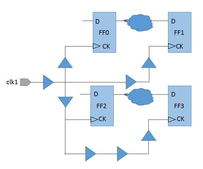
Clock skew is the difference in arrival time of clock signal at different sink pins. Clock skew concept can be better understand from figure 1.

As it can be seen from above figure that all the registers are placed at different distance from thee clock port. So time taken by clock signal to reach the clock pin of these registers will also be different. This time difference in arrival of clock signal is known as clock skew. Clock skew can be computed at two levels i.e. Global and Local.
Global clock skew is the difference in arrival time of clock signal between the shortest and the longest clock path in the same skew group. Timing path may or may not exist between these registers. In figure 2, skew between registers FF0 and FF3 is global skew.
Local clock skew is the difference in arrival time of clock signal between any two registers which shares a data path in a skew group. In figure 2, skew between registers FF0 and FF1 (or between FF2 and FF3) is called the local skew.
In figure 2, if we consider timing path between FF0 and FF1, then from figure it is quite obvious that clock will reach flop FF0 faster as compared to flop FF1. This skew, where clock arrives first at the launch flop than at capture flop, is known as Positive Skew. Whereas if clock arrives early at the capture flop than that at the launch flop, it is termed as the Negative skew. Positive skew is useful in reducing setup timing violations while negative skew is helpful for reducing hold timing violations.
Target of CTS is to build clock network in such a manner that clock skew should be as minimum as possible so that all the registers in the block can trigger at the same time. To achieve zero skew is not possible practically due to different delay offered by nets. This means even if net length and metal layers used is same for two different paths, they exhibit different delays owning to on-chip variations (OCV). Also it is not advisable to have zero skew. Reason being, zero skew means all the flops will turn on at the same time thus consuming power from the PG rail simultaneously. This increases the load on PG rails to supply power to all the flops at the same time. This can lead to major IR drop and can affect the chip functionality. Thus ideal practice is to maintain skew as minimum as possible. There are certain situations in which deliberately skew is provided to fix timing violations which is known as useful skew, this will be discussed later in STA section separately.
In a nut shell we can say that zero skew is not possible and advisable as well. Keeping skew constraint very high can lead to insertion of more number of clock buffers in clock path. This can again lead to more power drop and higher area requirement. Also too much tighter skew constraint can lead to more timing violations. Thus, it is highly advisable to keep skew at the optimum value so that desirable PPA parameters can be easily achieved.
Some factors that can affect clock skew are as below.
Unbalanced clock structure
On-Chip Variation (OCV) parameters
Registers belonging to same skew group are placed far
Unequal delay balancing at sink pins
Clock Latency
Clock latency is defined as the time taken by the clock signal to reach to the sink pin from its source. There are two types of clock latency i.e. Source and Network Latency.
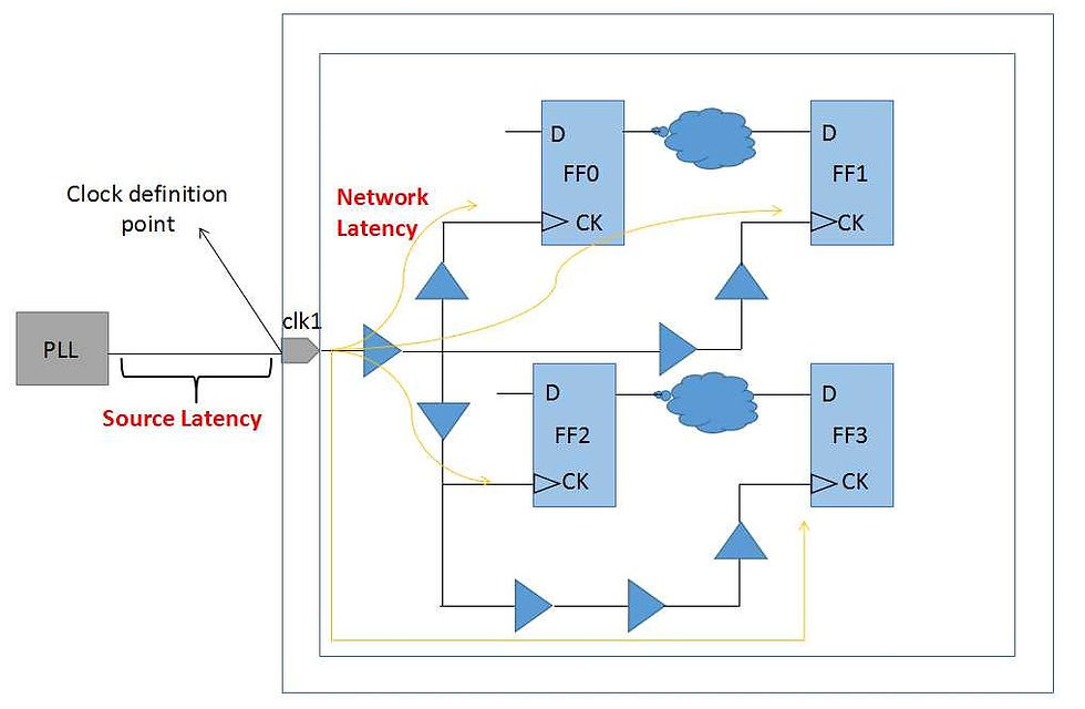
Clock Source Latency is the time taken by the clock signal to reach the clock definition point in the block from the clock source.
Clock Network Latency is the time taken by clock signal to reach the sink pin from the clock definition point in the block. Indicated by orange arrows in figure 3.
At block level we cannot control the source latency but we can definitely control the network latency. From here onward network latency will be termed as only latency for simplicity. There lies a trade-off between latency and skew. Sometimes to control the skew more buffers are required in clock path which means more insertion delay (or latency). More insertion delay means more area and power consumption.
Insertion delay is nothing but the actual clock path delay from clock port to the sink pin. Latency is the target provided to tool that how much maximum insertion delay it can add to any clock path. Latency target provided to CTS is same for the longest and the shortest path. In order to reduce insertion delay for some shorter paths, designer can explicitly specify the lower value of insertion delay for these paths.
In short we can conclude that more insertion delay means more number of clock buffers or inverters will be required which in return increases area, routing resources, and power consumption.
Some parameters affecting the insertion delay are as below.
Scattered registers
Long routes increasing RC delay of net
High clock fanout
More number of buffers/inverters added to meet skew target
Improper clock structure
Clock Uncertainty
There are various factors that can affect the clock period. These factors reduces the effective available clock period which in turn increases pessimism in the design. One such factor is clock jitter. Fluctuation of the clock edge from its ideal position is termed as clock jitter. For example, a clock period of 1ns having 50% duty cycle should have first rising edge at 0ps, first falling edge at 500ps and second rising edge at 1ns. Deviation of rising/falling edge from its ideal time period is called jitter. Refer to figure 4 for pictorial explanation of jitter concept.
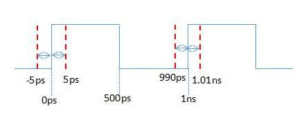
As seen in figure 4, 0ps is the ideal time for first rising edge but it can occur even before expected time that is why it is indicated as -5ps (early first clock edge). Red dashed line in above figure indicates that clock edge can occur at plus or minus Xps than the ideal time. For worst case analysis, we will consider launch clock edge at 5ps and capture clock edge at 990ps hence reducing ideal clock period by 15ps. Similarly we can also calculate clock jitter for falling edge as well. Clock jitter arises due to error in correction at the PLL from where clock is generated.
Clock jitter and other parameters which can impact effective clock period are modelled as clock uncertainty in SDC file. Prior to CTS clock uncertainty value is set higher than that of post-CTS stage. Reason being clock is ideal in pre-CTS stage so clock uncertainty has to account for clock network delays as well. Once clock network is routed, we have exact values for clock network delay. Thus, only jitter and other pessimism need to model in clock uncertainty in post-CTS stage.
During setup analysis, clock uncertainty value is subtracted from clock arrival time (reducing effective clock period for worst case analysis) while during hold analysis clock uncertainty value is added into the arrival time (again for worst case analysis).
This blog again contains some basic concepts that one should understand properly in order to analyse the clock reports. As clock skew and the clock latency are main targets to be achieved in CTS stage, it requires a detailed understanding of these parameters. Clock uncertainty impacts timing so it also becomes an important parameter to understand. Hope you find this blog informative and worth learning.
Quick Questions
In order to make posts interactive and making it a knowledge sharing platform, I am presenting few important questions from the topics of this blog.
Why hold timing is not checked in pre-CTS stage?
You might have often heard that hold timing is independent of clock. Is there any way by which we can fix hold timing making some changes in clock? If yes than how?
Consider two scenarios as below, which one would you prefer and why?
Clock skew = 90ps ; clock latency = 150ps
Clock skew = 45ps ; clock latency = 300ps
You can share your answers in comments section below. Let us share our knowledge and learn from each other. Thank you...!! :)


Yes hold is independent of timing as Required arrival time of hold is t(hold) itself to reduce hold violation push capture pull launch there making sure skew is positive so increase launch flop latency (pull launch) and decrease capture latency (push capture)
Slack
Tcq + Tcombo - Thold-skew
Slack = Tcq+ Tcombo - (Tcap- Tlaunch)
(Tcq+ Tlaunch)- ( Tcombo - Tcature)
In pre CTS stage hold is not checked because we don't insert buffers and after post CTS stage insertion of clock buffers reduces hold violation
Latency is higher priority compare to skew. so i go with a. Clock skew = 90ps ; clock latency = 150ps. it's correct? & if not give the suggestion.
The percentage you mentioned for skew and latency is correct. We always try to keep skew as low as possible as it is helpful to achieve timing requirements. Thus, option b will be helpful if we are not able to meet timing requirements. Higher latency will definitely lead to more IR drop. So, we have to choose based on timing and power requirements.
Ansi is option a because of target skew is 10 to 12 percentage of clock and target latency is 30 to 33 percentage