
Introduction to Netlist (.v), LEF, and DEF Files
- saumil vora

- May 29, 2020
- 7 min read
Updated: Mar 30, 2021
Greetings Readers!!! :)
This blog will give you insight about few very important files used in physical design cycle. This blog is limited to 3 files mentioned below.
Gate Level Netlist (.v)
Library Exchange Format (LEF)
Design Exchange Format (DEF)
After reading this blog readers will become familiar with the contents of each file mentioned above and their importance.
1. Gate Level Netlist (.v) :
The gate level netlist required to start PD flow is provided by synthesis team. That is why this file is also known as synthesised netlist.
It contains information about sequential gates, combinational gates, their connectivity, and logical hierarchy.
For eg. gate level netlist of a multiplexer using NAND gates will look like:
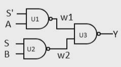
module mux(input S', A, S, B
	output Y)
		wire w1, w2
		nand U1(w1,S',A)
		nand U2(w2,S,B)
		nand U3(Y,w1,w2)
endmodule
In hierarchical design several modules are present (like in above example mux module is shown), PnR tool fetches hierarchy information from netlist.
One can also determine number of standard cells being used in design from netlist.
2. Library Exchange Format (LEF):
LEF file can be categorized into two parts i.e. Technology LEF and Cell LEF
Technology LEF:
Technology LEF file contains information about technology site, available layers for routing, layer's physical information (pitch, width, spacing, mask, direction etc.), DRC rules, VIA definition, Non-Default Rules (NDR).
This file is provided by foundary.
A technology LEF file contains below sections:
VERSION statement
Specifies the version of LEF syntax such as 5.6/5.7/5.8 .
With each version change there is syntax update.
BUSBITCHARS statement
Specifies the pair of characters to be used to represent bus bits in LEF file. Characters must be enclosed in double quotes. For eg. by defining BUSBITCHARS "[ ]" will allow [ ] to be used to define a bus.
Each bit in a 4 bit bus named bus_wire can be described as: bus_wire[0], bus_wire[1], bus_wire[2], bus_wire[3].
DIVIDERCHAR statement
Specifies the character used to separate hierarchy while mapping LEF names. Character must be enclosed in double quotes.
DIVIDERCHAR "/" will make use "/" (forward slash) as hierarchy separator. For eg. topModule/subModule/subsubModule
UNITS statement
Defines units of measurement for TIME, FREQUENCY, CAPACITANCE, RESISTANCE, POWER, VOLTAGE, CURRENT, DATABASE MICRONS
MANUFACTURINGGRID statement
Defines the manufacturing grid for design. When cells are placed in design they snap to this manufacturing grid.
USEMINSPACING statement
Defines minimum spacing for blockages.
This data will be considered while checking DRC.
CLEARANCEMEASURE statement
Defines the clearance spacing requirement for all object spacing in SPACING and SPACINGTABLE statements.
PROPERTYDEFINITIONS statement
Lists of all the properties used in LEF file. Property must be defined in this section before referring it to any other LEF section.
LAYER statement
Defines physical attributes for cut layer, implant layer, masterslice layer, and routing layer.
Physical attributes include, width, spacing, layer name, mask information (in case of double patterning designs), pitch, direction, DRC rules (min spacing, min area, min width, etc.)
MAXVIASTACK statement
Specifies the maximum number of single-cut via allowed on top of one another (max stack of VIA).
VIA statement
Both, generated and fixed via are defined in this section.
Specifies bottom metal layer, top metal layer, via cut information, cut spacing, via enclosure dimension, via offset, and cut pattern for all via.
VIARULE statement
Defines which via to be used when two wire shapes of same net intersects.
Rules described in this section are taken into consideration by tool by verifying DRC for via.
VIARULE GENERATE statement
Rules for generating via arrays are defined in this section.
VIARULE GENERATE statement is explicitly used to generate rules for special wires which are not defined in VIARULE statement section.
NONDEFAULTRULE statement
Defines special rules for wire spacing, width and via size.
These rules can be applied to nets which causes signal integrity violations.
Some example of NDR are: double width single spacing, single width double spacing, double width double spacing, etc.
While defining NDR, one must specify rule name, layer name, spacing rules, width rules, via name, via rules.
SITE statement
Defines placement site in the design.
Information specified in this section are: site name, site width, row height, site symmetry, row pattern.
BEGINEXT statement
This section defines the extension statements which can be used to define customised syntax into LEF file.
LEF syntax keeps on updating which is included in new LEF version release. To accommodate future LEF syntax in older LEF file, BEGINEXT extension statements can be used.
END LIBRARY
Defines the end of LEF library.
It is not mandatory that a LEF file has all the above mentioned sections. Few sections can be omitted.
Extension of a technology LEF file is .tf .
Cell LEF:
Cell LEF file contains information about abstract view of macro and standard cells. There is separate LEF files for macros and standard cells.
Standard cell LEF file is provided by foundary, macro LEF file will be provided by foundry or third party vendor in case macros/IPs are obtained from them.
Sections in a Cell LEF file are as below. Sections other than MACRO in below list have same functionality as stated for tech LEF file above.
VERSION statement
BUSBITCHARS statement
DIVIDERCHAR statement
VIA statement
SITE statement
MACRO statement
Defines the macro/standard cells in design.
This section contains information regarding attributes of cells such as name, class, size, symmetry, site, pin statements, OBS (obstruction layers) statement, etc.
PIN statements includes pin names, coordinates (size), layers, direction (in/out/inout), use (signal/clock/power/ground).
Also defines antenna rules in pin's section.
BEGINEXT statement
END LIBRARY
Here also all statements are not mandatory as explained for tech LEF.
Extension of CELL LEF file is .LEF .
LEF file is written in ASCII format.
In ICCII tool, .CELL and .FRAME binary files are used instead of .LEF files. Advantage of using binary file is that it can be read faster by PnR tool and requires less storage space comparatively.
If you want to find out standard cell and macro area even before starting floorplan stage then that can be done by using information from netlist and CELL LEF files. From netlist we can get actual count of standard cells and macros used in design while area of these cells can be obtained from CELL LEF file. Combining these information one can calculate total core area required by cells in your design.
3. Design Exchange Format (DEF):
DEF file contains placement data of all the physical objects present in the design.
As netlist includes logical connectivity, hierarchy information and physical constraints, similarly DEF file contains placement locations, orientation, routing geometry information.
Sections included in DEF file are as below. Order of statements can be changed but data must be defined before it is used.
Sections such as VERSION, DIVIDERCHAR, BUSBITCHARS are same as explained in LEF file.
VERSION statement
DIVIDERCHAR statement
BUSBITCHARS statement
TECHNOLOGY statement
Specifies technology name for design in data base.
UNITS statement
Specifies database units per microns to convert DEF db units into microns.
For eg. if UNITS 2000 is defined in DEF then it means distance of 12000 units in DEF is equivalent to distance of 6 microns (12000/2000) in PnR tool.
PROPERTYDEFINITIONS section
In this sections all the properties are listed.
Information like object type (component, pin, net, region, etc.), property name, property type (string, integer, float), property value are specified in this section.
DIEAREA statement
Specifies the coordinates of die.
In case of rectangle die four coordinates will be specified and if it is more means it represents a rectilinear die shape.
Coordinates unit will be as per specified in UNIT section.
ROWS statement
Defines rows in the design.
Row attributes such as row name, site name, number of rows, row orientation, direction (horizontal/vertical), row height are stored in this section.
TRACKS statement
This section describes the routing grid of the design.
Track orientation (X/Y), layer name, number of tracks, track pitch are described in this section.
GCELLGRID statement
Defines the GCELL grid for design.
A GCELLL grid is formed by number of horizontal and vertical tracks.
VIAS statement
This section contains the list of via names and via geometry information used in design.
One can find via cut layer, cut size, bottom routing layer, top routing layer, via enclosure information, via offset from this section.
STYLES statement
Defines the convex polygon defined at the each endpoints of a wire.
NONDEFAULTRULES statement
All the non default rules used in design, whether it is specified in LEF file or not, are stored in this section of DEF file.
REGIONS statement
Any region specified in the design is described under this section.
Saves region coordinates, its type and properties.
A region is a physical area in which group of cells are placed.
COMPONENTS section
All the physical attributes (cell type, name, physical status, orientation, halo, region, etc.) of components used in design are described in this section.
It includes macros as well as standard cells.
PINS section
Describes all IO ports in the design, their properties and antenna rules associated with each port.
PINPROPERTIES section
Specifies all pins for each component in design along with their attributes.
BLOCKAGES section
Lists placement and routing blockages used in design and all the physical attributes associated with them.
SLOTS section
If slots are created for wire shapes in the design then they are represented here in rectangular form.
FILLS section
Metal fills in the design are listed here. Each metal fill is represented by a rectangle.
SPECIALNETS section
Describe the connectivity of nets connected to special pins such as PG pins.
NETS section
Defines the connectivity of nets as given in netlist.
All the physical attributes if each net are also defined along with net name.
SCANCHAINS section
Defines scan chain cells used in the design.
Scan cell pins are defined in PINS section with +USE SCAN attribute.
GROUPS section
Defines groups in a design.
It includes regions specified in the design and components associated with that region.
In REGIONS section described above, information regarding cells associated with the region is not included.
END DESIGN statement
End design statement
Also END statement is used at the ending of each section. For Eg., components section can be written as:
COMPONENTS 2
- u1 AND +PLACED (50 50) N
- u2 BUFF +PLACED (35 120) N
END COMPONENTS
Apart from above mentioned files there are other important files, such as Liberty file (.lib), SDC file, UPF file, and RC extraction file, which are needed to kick start a PD flow. As these files require a lot of details to cover, I am planning to have an individual post for each of them.
If you want to discuss more on input files described in this blog please feel free to mention in comments or you can always contact me. I will try to answer as per my knowledge, We will meet again in next blog till then STAY HAPPY, STAY SAFE, and KEEP LEARNING!!! :)


Comments